NeXT Pi
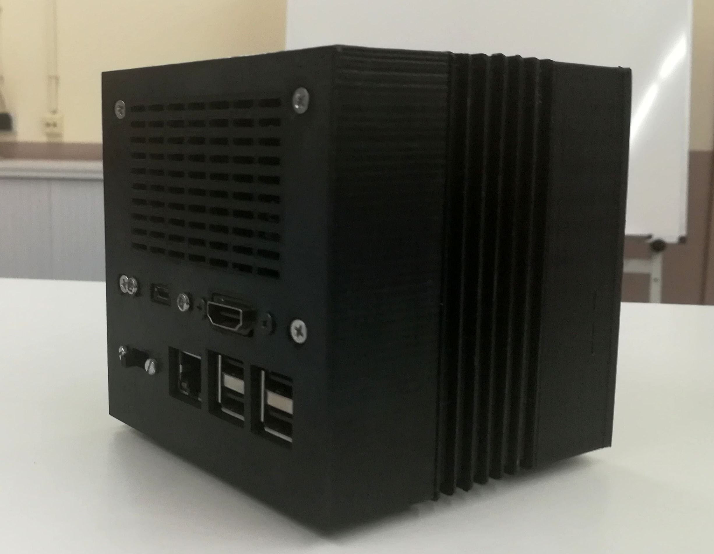
NeXT Computer (also called the NeXT Computer System) is a workstation computer that was developed marketed, and sold by NeXT Inc. This is a write-up of a maker project to replicate the original NeXT computer (plus some mods) with a Raspberry Pi.

A NeXT Computer and its object oriented development tools and libraries were used by Tim Berners-Lee and Robert Cailliau at CERN to develop the world’s first web server software, CERN httpd, and also used to write the first web browser, WorldWideWeb. – from Wikipedia
This project is based on a previous and very similar one by Nina Richards. I will not focus on the 3D parts since they are well described on the mentioned blog post by Nina Richards.
Parts
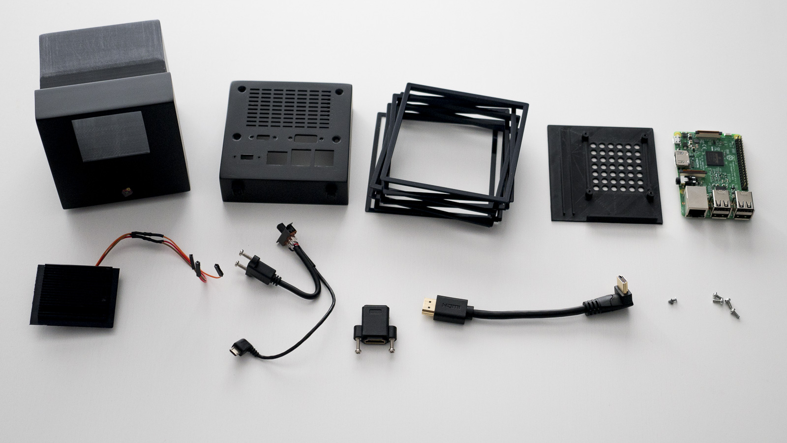 Image credits to Nina Richards.
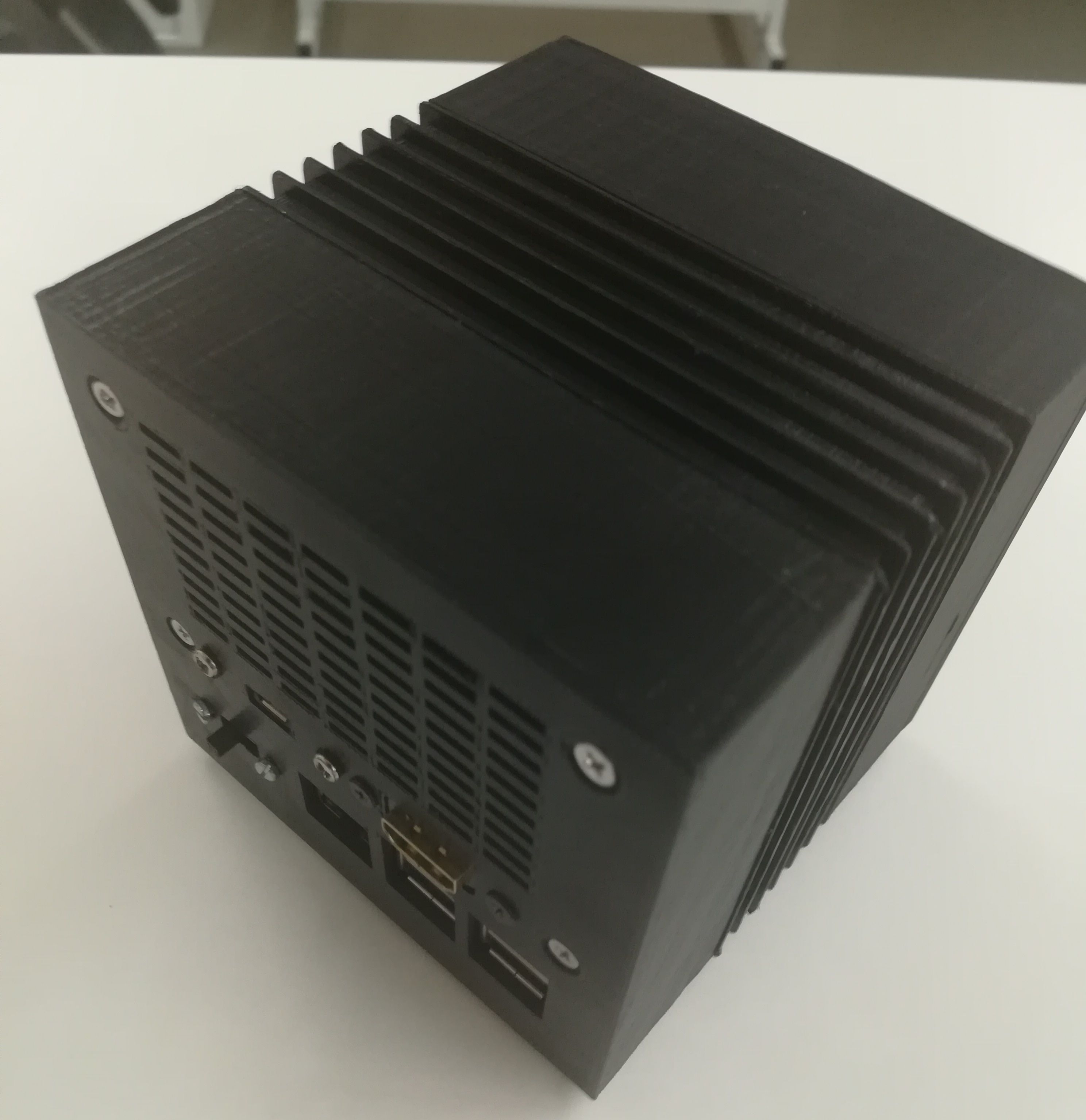
3D Parts
| Count | Part |
|---|---|
| 1 | Front/Body |
| 1 | Front Panel (Grid) |
| 1 | Tray |
| 6 | Fins with spacers |
| 1 | Fin |
| 1 | Back Section |
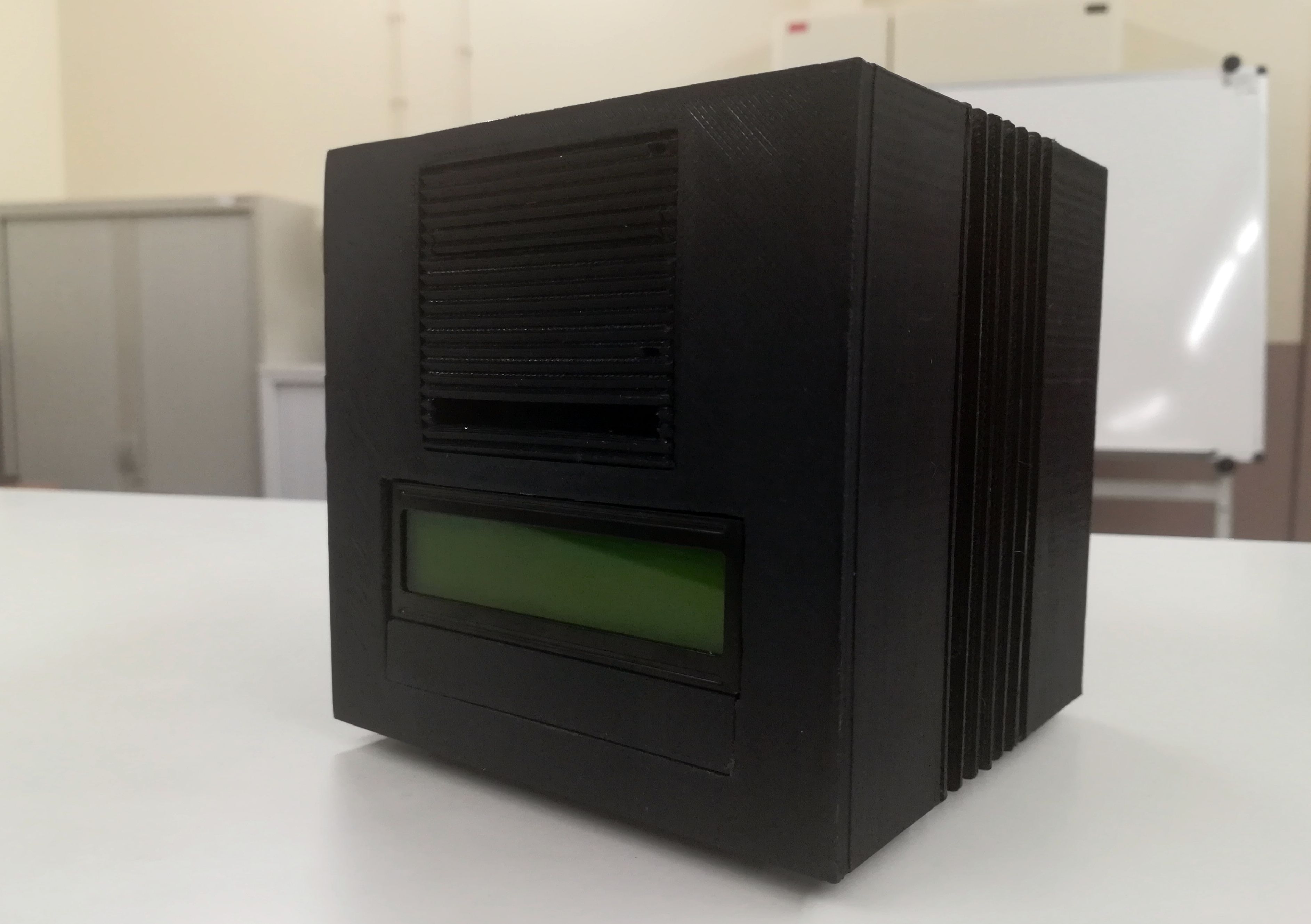
All the 3D model STLs are available on Thingiverse. The mod of having the 16x2 LCD required drilling a hole on the Front/Body part, the new STL will be shared eventually.
Other Parts
| Count | Part |
|---|---|
| 1 | Raspberry Pi 2 (compatible with version 3) |
| 2 | 3mm LEDs (or similar) |
| 3 | Female header connectors |
| 2 | 82Ω Resistors |
| 1 | Power Switch |
| 1 | Panel Mount micro-USB socket |
| 1 | micro-USB cable |
| 1 | Panel Mount HDMI socket |
| 4 | 5mm heat-set brass threaded inserts with M3 thread |
| 4 | M3 6mm countersunk screws |
| 4 | 3mm x 4mm self-tapping screws |
| 4-8 | Heat-shrink tubes |
| 1 | 16x2 LCD with I2C |
All the parts were brought in Aliexpress. You can easily find similar ones on eBay, Amazon or any other hardware parts seller.
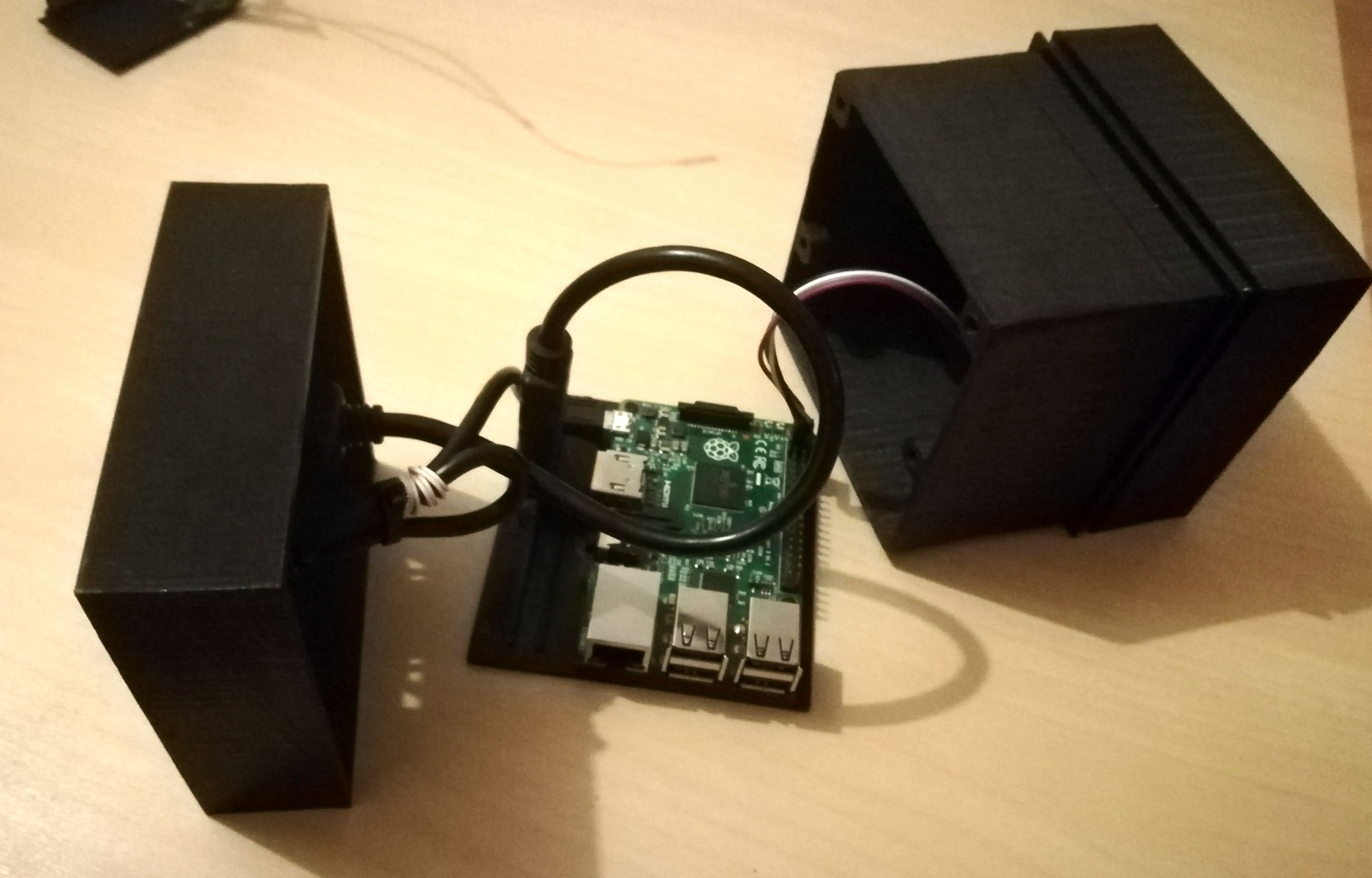
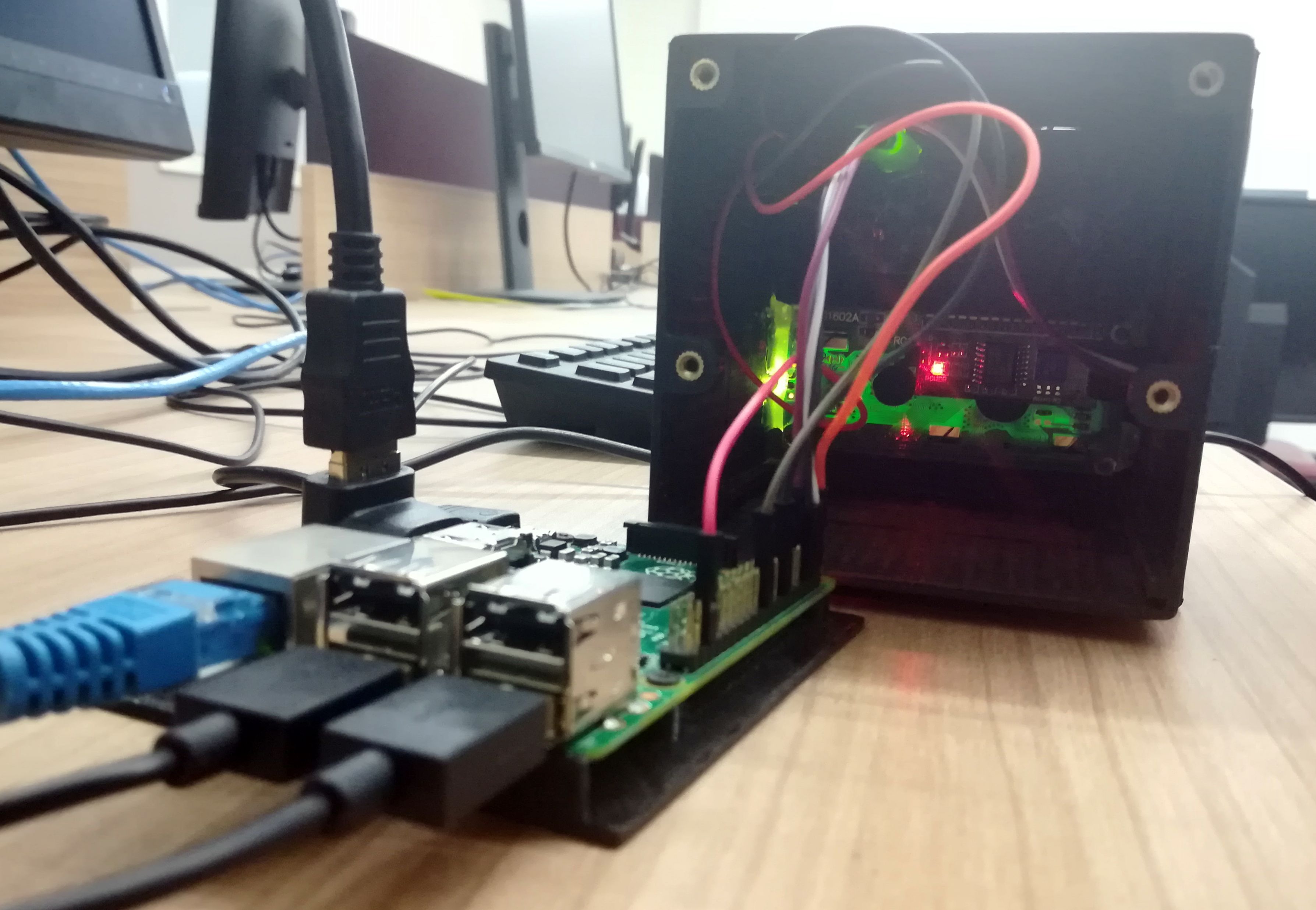
Mount Instructions
Wiring Diagram
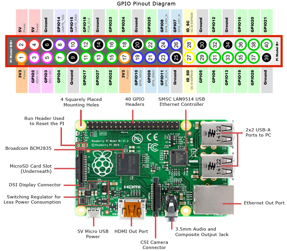
Raspberry Pi 2 Schematic
Fritzing Wiring Diagram
Changing the Activity LED default GPIO
To change the status LED from the default on-board LED to the new one that fits on the Front Panel we need to change the deafult GPIO connector. For that purpose, just edit the file /boot/config.txt and set the following value to the respective new GPIO (in the schematics above it’s the GPIO 16):
dtparam=act_led_gpio=16
Configuring the I2C LCD
[1] Configure the I2C Interface
- Activate I2C communication on the Raspberry Pi.
- Guided Mode:
$ sudo raspi-config- 5 Interfacing Options
- Yes for enable I2C
- Yes for automatically loading the kernel module
- Finish & Reboot
- Manual Mode:
- Edit the
/boot/config.txtfile and setdtparam=i2c_arm=on - Edit the
/etc/modulesfile and add linei2c-dev - Reboot
- Edit the
- Guided Mode:
[2] Install Dependencies
1
2
3
4
5
6
7
$ sudo apt-get install i2c-tools
$ sudo apt-get install python-smbus
$ sudo modprobe i2c-dev

$ i2cdetect -y 1 # get I2C address param 0 if rp1

$ wget https://raw.githubusercontent.com/emcniece/rpi-lcd/master/RPi_I2C_driver.py #change I2C address
[3] Sample Scripts
Hello World on LCD:
1
2
3
4
5
6
import I2C_LCD_driver
from time import *

mylcd = I2C_LCD_driver.lcd()

mylcd.lcd_display_string("Hello World!", 1)
Showing Local IP Address:
1
2
3
4
5
6
7
8
9
10
11
12
13
14
15
16
17
18
import I2C_LCD_driver
import socket
import fcntl
import struct
mylcd = I2C_LCD_driver.lcd()
def get_ip_address(ifname):
s = socket.socket(socket.AF_INET, socket.SOCK_DGRAM)
return socket.inet_ntoa(fcntl.ioctl(
s.fileno(),
0x8915,
struct.pack('256s', ifname[:15])
)[20:24])
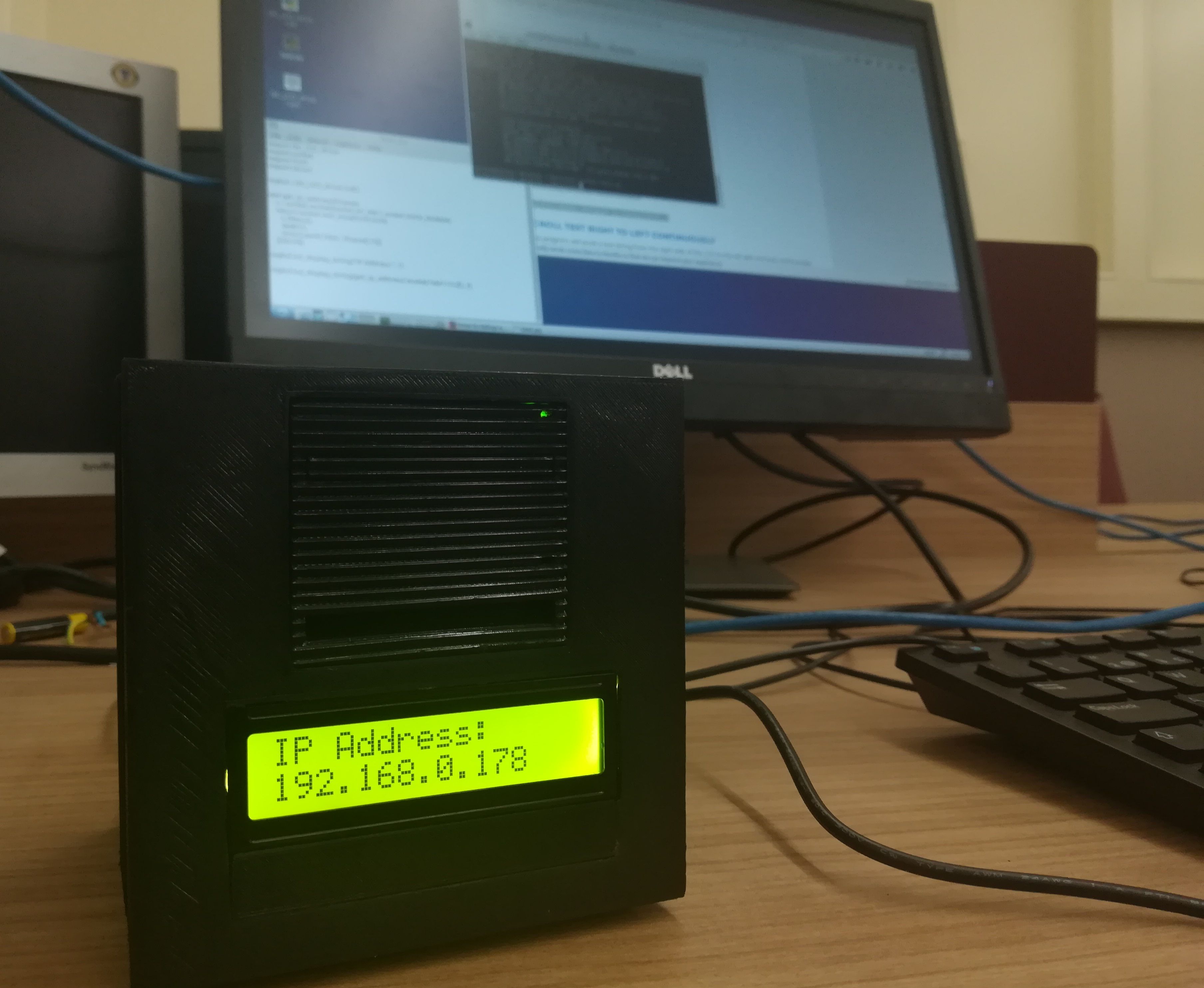
mylcd.lcd_display_string("IP Address:", 1)
mylcd.lcd_display_string(get_ip_address('eth0'), 2)
[4] Troubleshooting
It’s possible that the 16x2 LCD will be misconfigured at the contrast level. To adjust it, just turn the potentiometer screw of the I2C conversor (on both directions) until you get the right contrast (positioned in the back of the LCD).
Assembly & Final Result