Indoor Sensing Hub powered by Mozilla Things Framework
The Web of Things aims to build the Internet of Things in a truly open, flexible, and scalable way, using the Web as its application layer. Empowering this idea, Mozilla has been making efforts towards a Web of Things standards, providing a gateway implementation along with libraries for the most common languages. In this blog post, we will go through the process of making a Web of Things device.

Before entering into the details of Web of Things1, one must present its origin, the Internet-of-Things. The Internet-of-Things can be seen as the result of the interconnection via the Internet of computing devices embedded in everyday objects, enabling them to send and receive data. This paradigm-shift provoked a ripple effect transforming everyday objects into smart objects, thus being widespread in terms of domains of application.
This paradigm-shift opened a window on new market opportunities that lead to several companies to create new products for these new markets, such as the smart-home. However, *despite utopian visions of seamless home automation, the smart home technology market, like every other, is fragmented*23. Several companies, institutions and other entities (including governmental ones) have been working on standards for assuring the interoperability and reducing the technological fragmentation of IoT.
Web of Things, as part of the Internet-of-Things initiative, proposes the creation a decentralized Internet-of-Things by giving Things URLs on the web to make them linkable and discoverable, and defining a standard data model and APIs to make them interoperable4.
Mozilla, as a defender of the mission of “keeping the internet open and accessible to all” and putting efforts on building a better Internet2 has embraced the Web of Things initiative and created Project Things4. This project distinguishes itself from the other standardization initiatives due to the fact that it is built upon existing web standards such as HTTP, REST, JSON, WebSockets and TLS.
Project Things4 is an experimental framework of software and services from Mozilla for connecting “things” to the web and will consist of three main components:
- Web Thing API: A common data model and API for the Web of Things.
- Things Gateway: An implementation of a Web of Things gateway that leverages the Web Thing API.
- Things Cloud: A collection of IoT cloud services.
- Things Framework: A collection of reusable software components for building Web Things, which directly expose the Web Thing API.
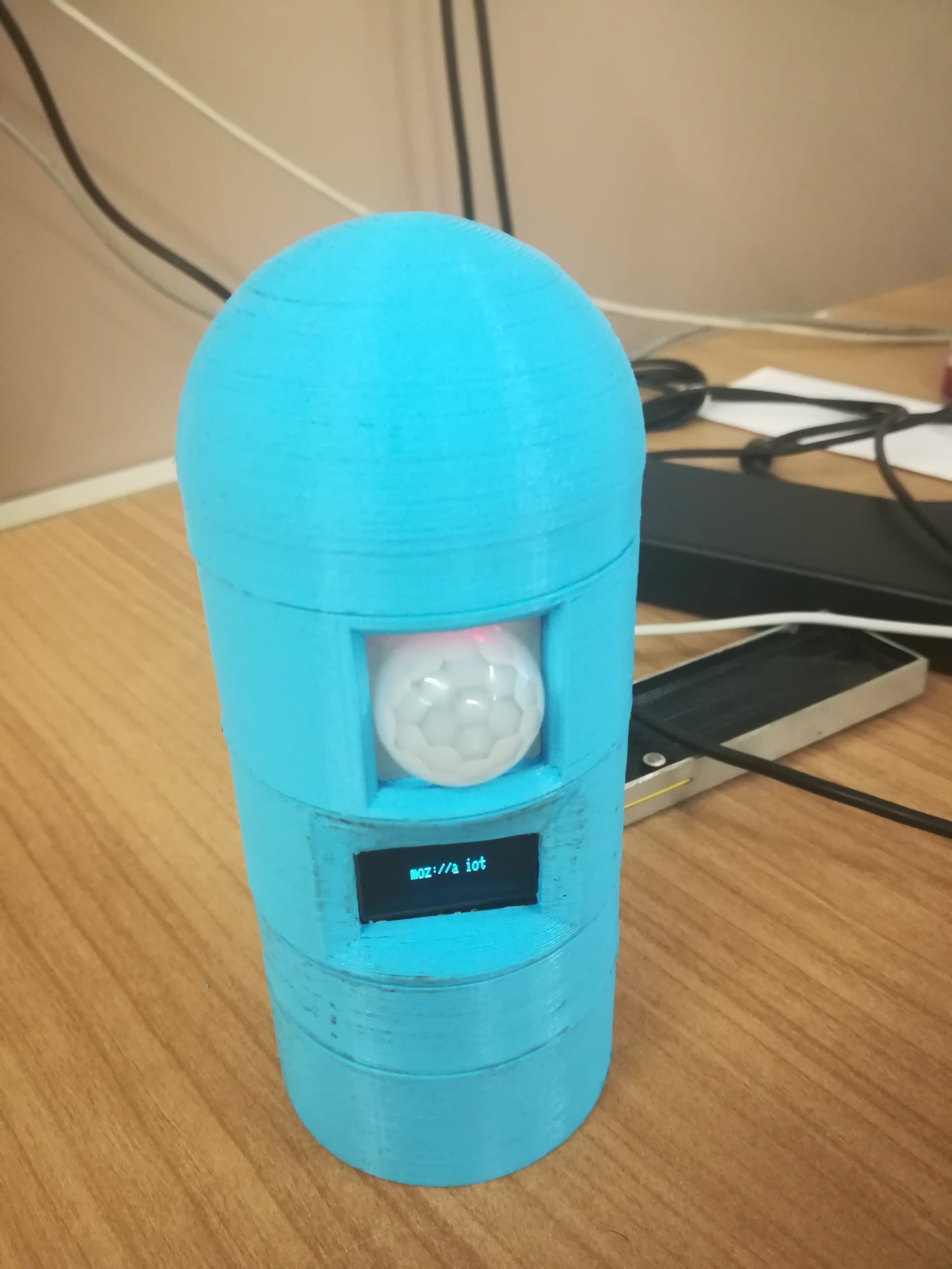
The goal of this project is to build a Web of Things device capable of sensing its surroundings by measuring temperature, humidity and sensing motion. Plus be able to show any information in an OLED screen and operating status in a LED.
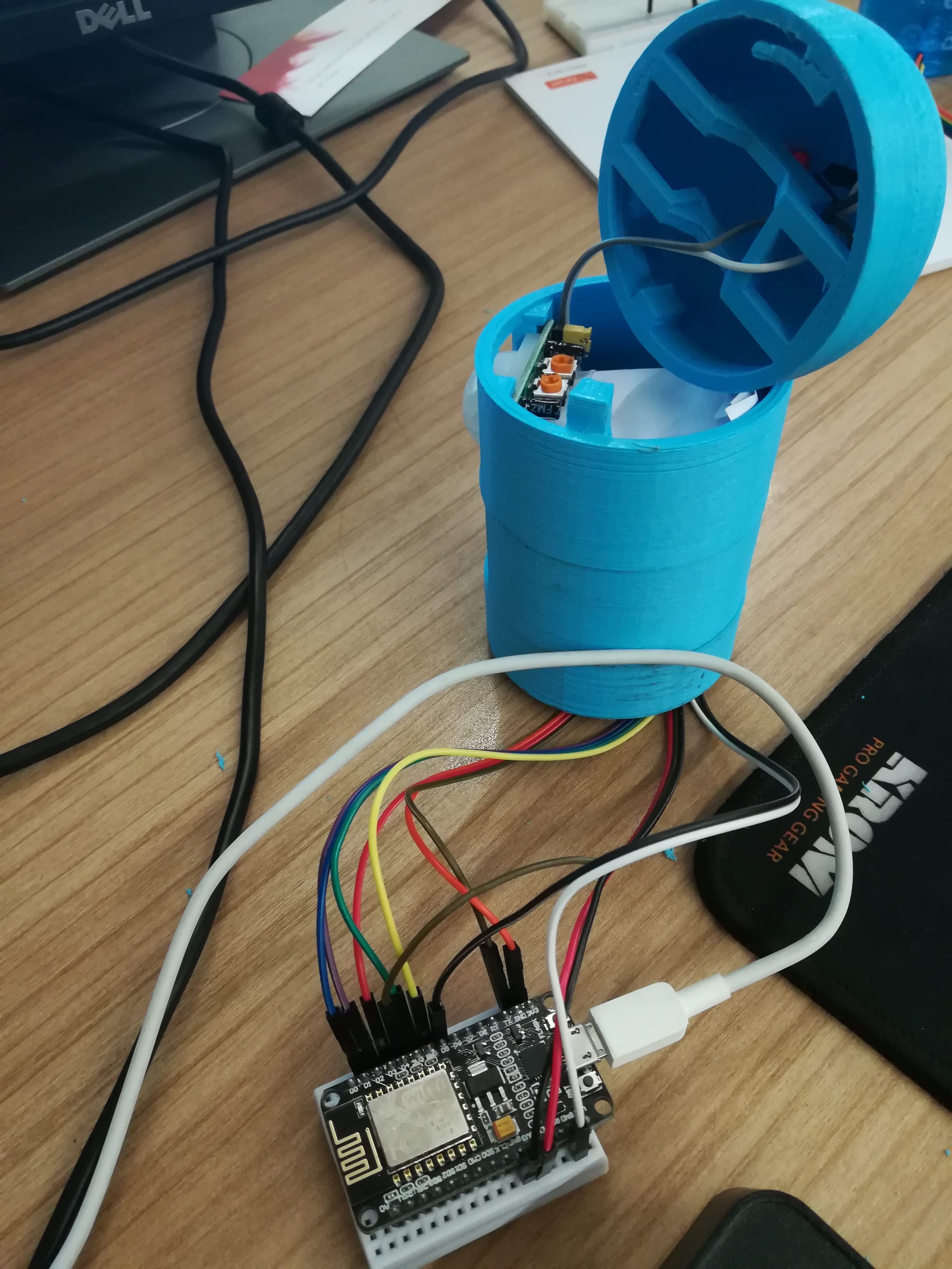
The Hardware
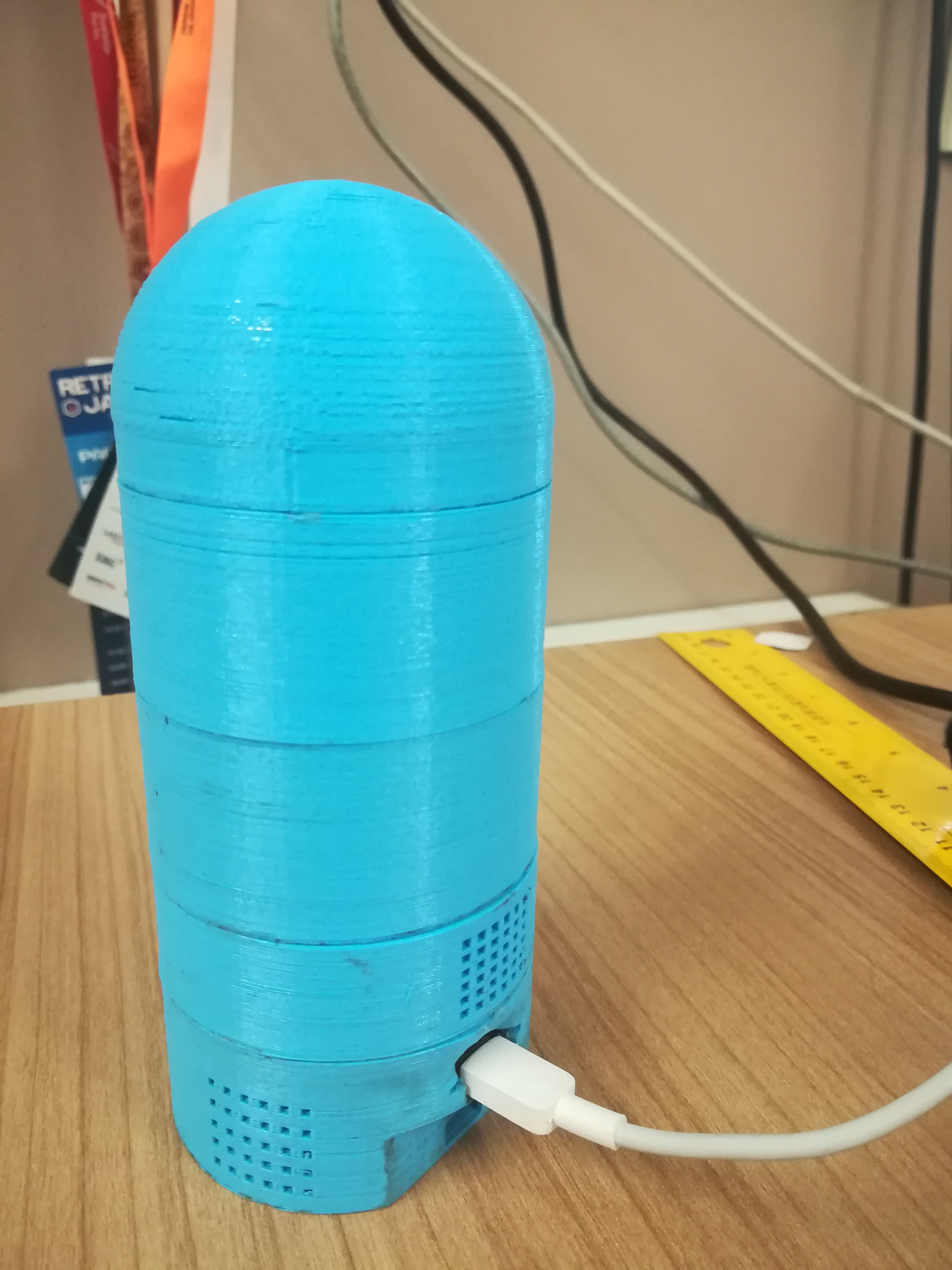
3D Printed Sensing Hub Box
After searching on Thingiverse we found out this cool 3D printed modular case for a NodeMCU ESP8266 microcontroller. Since it fits my goal of having multiple components, and, even, upgrade it with more components if needed, it was a go-go.
| Count | 3D Part |
|---|---|
| 1x | Base_NodeMCU |
| 1x | Dome |
| 1x | Temperature_sensor_module |
| 1x | Small_OLED_screen_module |
| 1x | PIR_module |
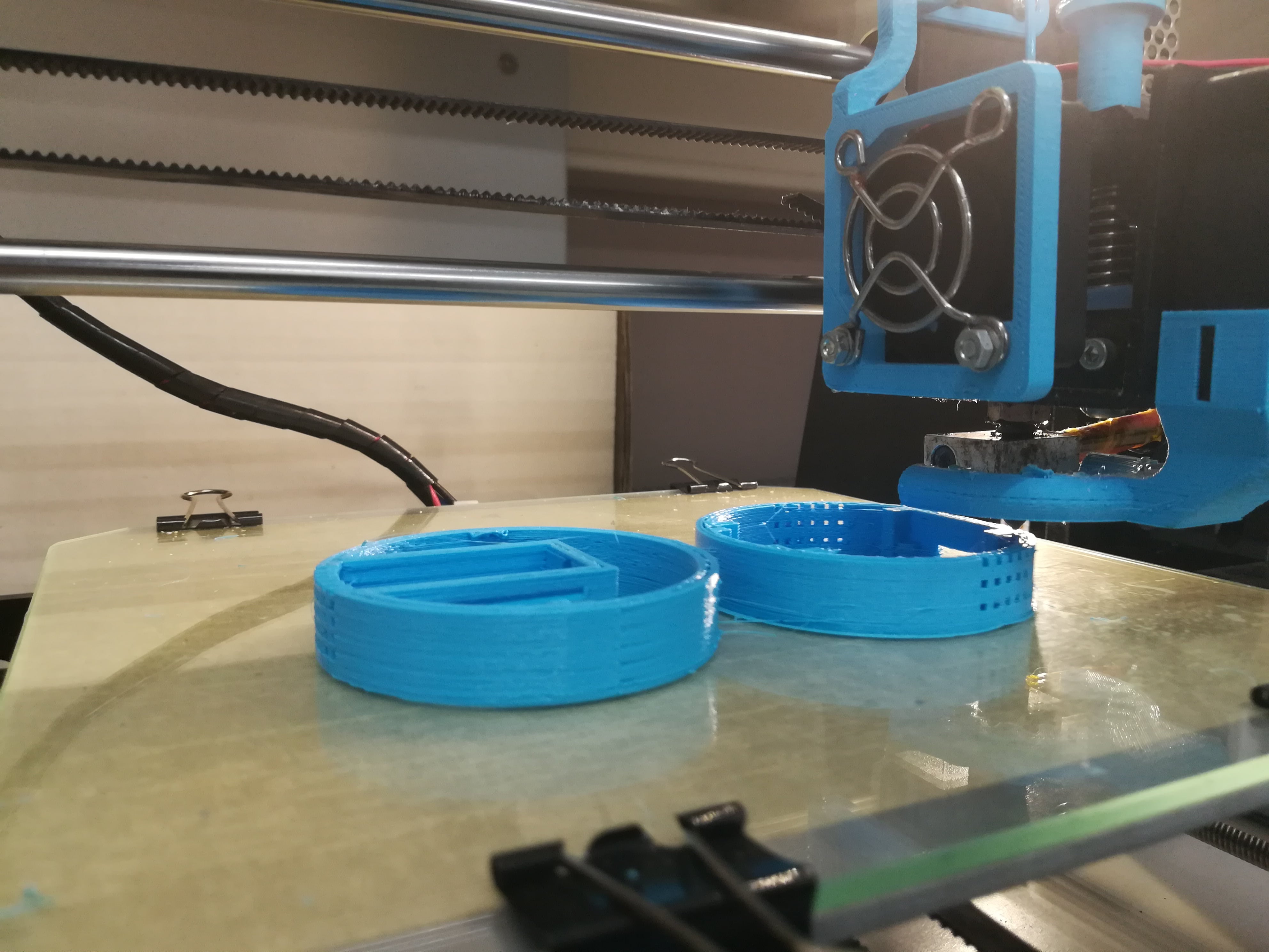
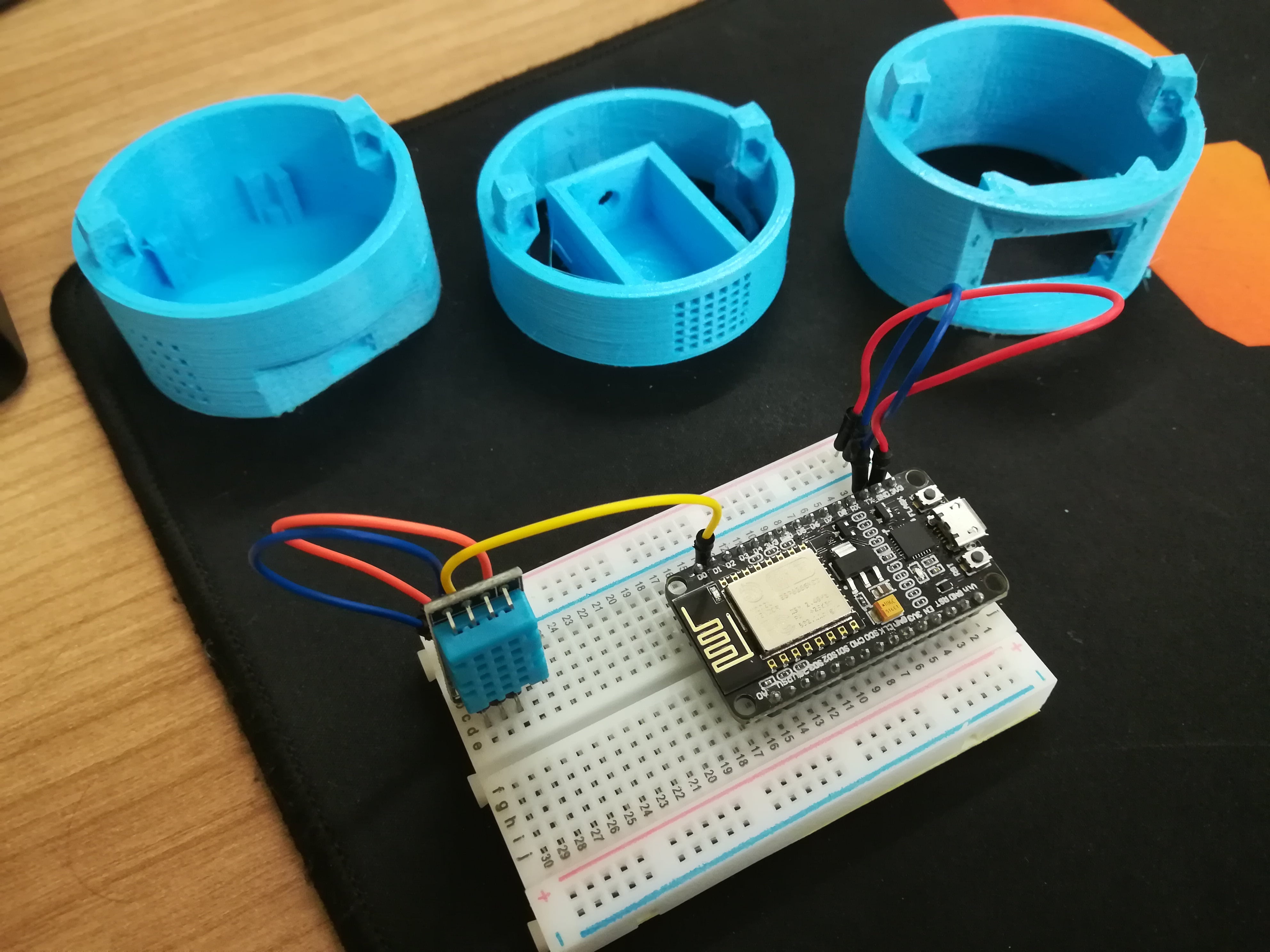
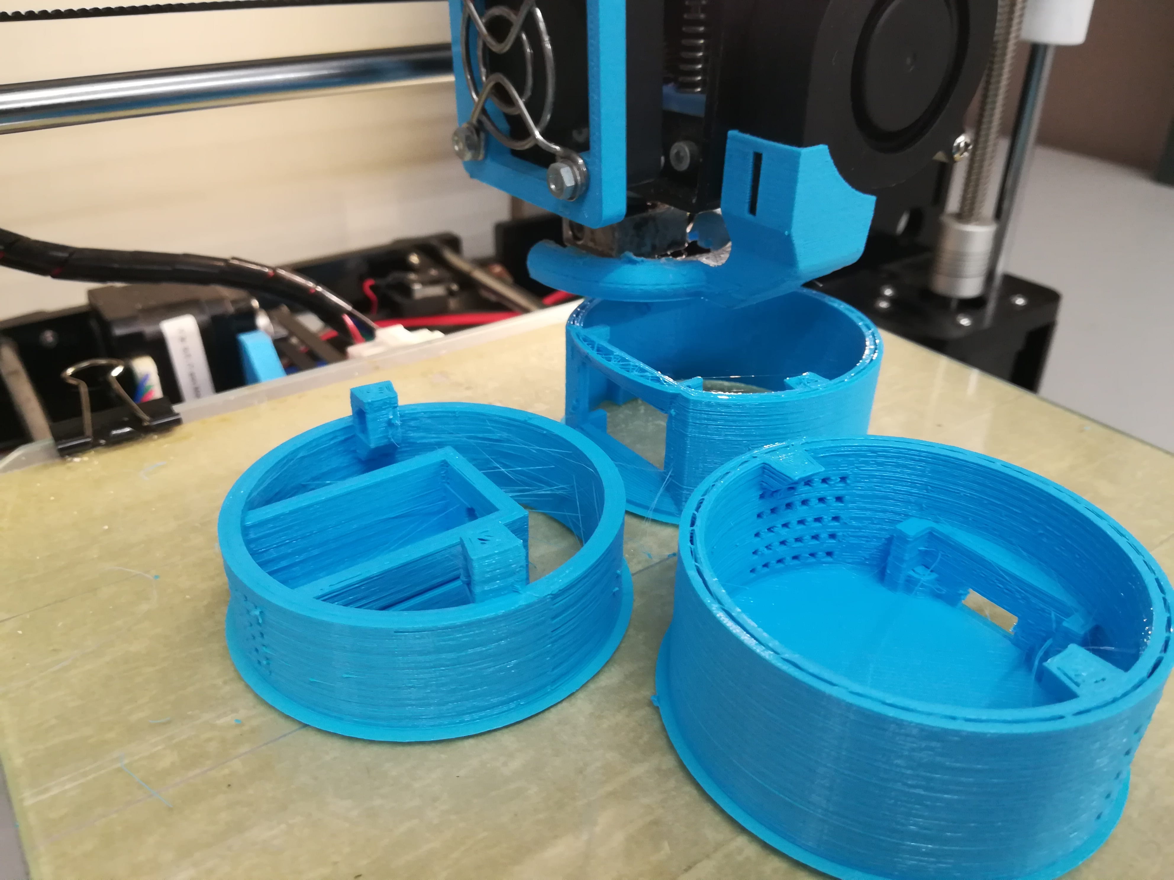
Some modifications were done to this models after printing for fitting a breadboard into the Base_NodeMCU. All the printing was done using an Anet A8 printer.
Parts and Circuits
| Count | Part |
|---|---|
| 1x | NodeMCU ESP8266 |
| 1x | LED (red) |
| 1x | PIR Motion Sensor |
| 1x | DHT11 Temperature/Humidity Sensor |
| 1x | 0.96” I2C OLED 128x64 Screen |
| *x | Jump wires (Male-Female) |
| 1x | Mini Breadboard |
The NodeMCU board was picked up since it is cheap, has a built-in wireless shield and is compatible with almost any Arduino libraries and scripts.
All the parts were brought on eBay. You can easily find similar ones on Aliexpress, Amazon or any other hardware parts seller.
If you want something more plug&play you can use the components from Seed Studio. They sell all the components above mentioned (including a PIR Motion Sensor) along with Grove hats that you can use to wire sensors and actuators more easily without need to worry about breadboards and so on.
The Software
Using the Mozilla Things Framework is as easy as adding the webthing-arduino and ArduinoJson libraries to the PlatformIO project. Further, for starting a web server in the NodeMCU the ESP Async WebServer is used.
For the sake of simplicity for reading and writing data from and to the different parts several libs were used, namely:
- ` DHT sensor library`: Reading data from the DHT sensor.
Adafruit GFX Library,Adafruit_SSD1306andOneWire: Writing data on the OLED screen using the I2C connection5.TaskScheduler: For scheduling recurring tasks (due to limitations of the DHT sensor, we cannot read data all the times, so we need to schedule it in the Arduino loop).
After setting up the dependencies, let’s focus on the main.cpp.
Setting up the Internet connection
Using the lib ESP8266WiFi we can set up the Wireless.
Defining the connection settings:
1
2
char *ssid = WLAN_SSID;
char *password = WLAN_PASS;
Setting up the connection:
1
2
3
4
5
6
7
8
9
10
11
12
13
14
15
16
17
18
19
20
21
22
23
void setup()
{
...
WiFi.begin(ssid, password);
...
while (WiFi.status() != WL_CONNECTED)
{
delay(500);
digitalWrite(STATUSLED, PIN_STATE_HIGH);
delay(500);
digitalWrite(STATUSLED, PIN_STATE_LOW);
delay(500);
}

    Serial.print("Connected to ");
    Serial.println(ssid);
    Serial.print("IP address: ");
    Serial.println(WiFi.localIP());

    digitalWrite(STATUSLED, PIN_STATE_HIGH);
    ...

}
And we’re now connected to the local network.
Creating a new WebThingAdapter (our web thing)
1
2
3
4
5
6
7
WebThingAdapter \*adapter;

void setup()
{
adapter = new WebThingAdapter("indoorsensor", WiFi.localIP());
adapter->begin();
}
From this point on we already have our thing being announced to the local network using mDNS6 and we can access the device on our browser using the address: http://indoorsensor.local. The result page presents a JSON (as defined by the Web Thing API) with information about all the devices (components) connected to our thing.
Adding components to our Adapter
This is an example of how to add the DHT sensor to the web thing. A similar process is needed for all the other parts.
1
2
3
4
5
6
7
8
9
10
11
12
13
14
15
16
17
18
19
20
21
22
23
24
25
26
27
28
29
30
31
32
33
34
35
36
37
38
39
40
41
const char \*dht11Types[] = {nullptr};
ThingDevice indoor("dht11", "Temperature & Humidity Sensor", dht11Types);
ThingProperty indoorTempC("temperatureC", "", NUMBER, nullptr);
ThingProperty indoorHum("humidity", "", NUMBER, nullptr);

void readDHT11data()
{
Serial.println("Updating DHT data.");
/_Serial.println("f-readDHT11data");_/

float h = dht.readHumidity();
/_Read temperature as Celsius (the default)_/
float t = dht.readTemperature();
/_Read temperature as Fahrenheit (isFahrenheit = true)_/

if (isnan(h) || isnan(t) || isnan(f))
{
Serial.println("Failed to read from DHT sensor!");
return;
}

ThingPropertyValue value;

value.number = t;
indoorTempC.setValue(value);
value.number = h;
indoorHum.setValue(value);
}

void setup(){

indoor.addProperty(&indoorTempC);
indoor.addProperty(&indoorHum);
adapter->addDevice(&indoor);

}

void loop(){
readDHT11data();
adapter->update();
}
Going through the code:
- Firstly we create a component of the thing with the
ThingDevice - Then we add the properties of that specific part with several
ThingPropertycalls. - We define a function to retrieve the sensor data
void readDHT11data():- In this function we create a new
ThingPropertyValue value; - For each value that we want to update or set we create a temporary variable with the value
value.number = t;and then set this value to the respectiveThingProperty,indoorTempC.setValue(value);.
- In this function we create a new
- In each loop we retrieve the values calling the respective function, in the case, the
readDHT11data()function. - At last, we update our adapter with the new data from the sensors.
Parts Detail
Connecting all the different components resulted in some extra effort due to particularities of them. Those particularities are described in the following paragraphs.
Reading data from DHT
All the DHT sensors have the need of setting a delay between reads. The documentation mentions a time of approx. 2000 milliseconds between reads. However, the execution period of each loop is lower than that, and it is not guaranteed the exact execution time (can depend on the hardware and components). In order to assure that we just try to read data from the DHT with a given periodicity (above 2000 milis in the case of DHT), we need to keep track of time.
Using the lib TaskScheduler we can easily create tasks that are executed just at a given time. As an example we can see the following code:
1
2
3
4
5
6
7
8
9
10
11
12
13
14
15
16
17
18
19
20
21
22
23
24
/_create task for readDHT11data,
that execute forever, at 5000 milliseconds intervals_/
Task t1(5000, TASK_FOREVER, &readDHT11data);
Scheduler runner; /_Setup of the task runner_/

void setup()
{
...
runner.init();
Serial.println("Initialized scheduler");

    runner.addTask(t1);
    Serial.println("added t1");
    ...

    t1.enable();
    Serial.println("Enabled task t1");

}

void loop(){
runner.execute();
...
}
Connecting the OLED Screen
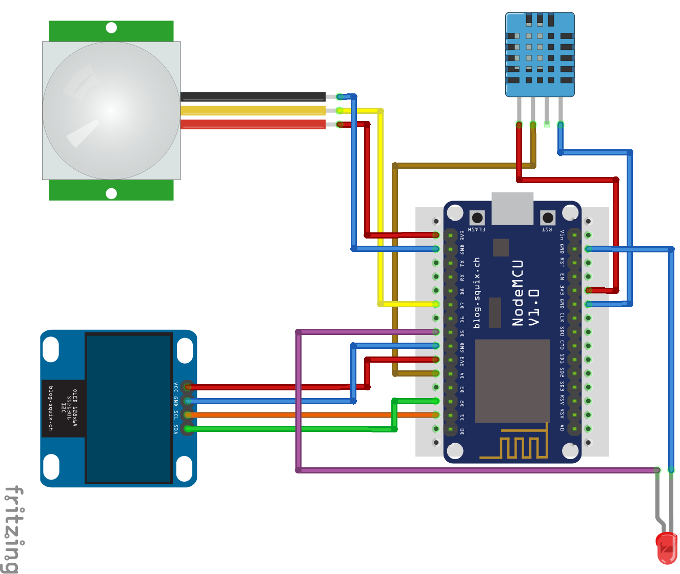
The OLED screen uses I2C communication (reducing the number of pins used). We have a 4 pin connection, the VCC, GND, Serial Data Line (SDA) and Serial Clock Line (SCL)5. Using the Adafruit_SSD1306 for connecting to it, we need to know the hardware address to communicate with it. For finding it out we can use the I2C scanner (gist available here) to check all the pins.
In NodeMCU boards it is recommended to connect any I2C devices to pins D1 and D2 (as presented in the above circuit schematic).
1
2
3
4
5
6
7
8
9
10
11
12
13
14
15
#define SCL_PIN 5 /_D1_/
#define SDA_PIN 4 /_D2_/
#define OLED_ADDR 0x3C

String lastText = "moz://a iot";

Adafruit_SSD1306 display(-1); /_-1 = no reset pin_/

void setup(){
display.begin(SSD1306_SWITCHCAPVCC, OLED_ADDR);
display.clearDisplay();
display.display();

displayString(lastText);
}
Going through the code:
- Init the
Adafruit_SSD1306lib. In our case the OLED screen doesn’t have a reset pin, so we need to pass a -1 to the function. - Start the display
display.begin(SSD1306_SWITCHCAPVCC, OLED_ADDR);` - Clean any data that could be on the display and display the data. In this case, the screen must remain empty.
- Call the function that writes to the screen
displayString(lastText); - The string moz://a iot should appear on the screen.
-> Bonus Tip
In our case, due to the screen used and printing details, we used our screen upside down, so we created a fork of the original Adafruit lib and added a void flip() function that redraws anything on the screen, making it readable in the right direction.
Checking for motion
Since the motion sensor can be triggered at any time, we can’t simply check for motion in the loop. For that purpose, we can use interrupts7. So, instead of using the common pinMode(PIR, INPUT);, we must use the INPUT_PULLUP flag. This allows us to hook a function when the value of the pin changes (flag CHANGE). Since we’re working with a digital input, this means that the value changes from 0 to 1 when it senses motion and makes a call to the motionDetectedInterrupt function.
1
2
3
4
5
6
7
8
9
10
11
12
int state = false;

void motionDetectedInterrupt()
{
Serial.println("Motion Detected!");
state = !state;
}

void setup(){
pinMode(PIR, INPUT_PULLUP);
attachInterrupt(digitalPinToInterrupt(PIR), motionDetectedInterrupt, CHANGE);
}
Our motionDetectedInterrupt function toggles the value of the global variable state when it senses motion, and, then, when it stops sensing it. Then we can easily read this state using the same approach that we used in the case of the DHT sensor, making the boolean data available by calling the respective endpoint.
All the code is available on GitHub.
Final Result
Resulting JSON Schema
1
2
3
4
5
6
7
8
9
10
11
12
13
14
15
16
17
18
19
20
21
22
23
24
25
26
27
28
29
30
31
32
33
34
35
36
37
38
39
40
41
42
43
44
45
46
47
48
49
50
51
52
53
54
55
56
[
{
"name": "Text display",
"href": "/things/textDisplay",
"@context": "https://iot.mozilla.org/schemas",
"@type": [
"TextDisplay"
],
"properties": {
"text": {
"type": "string",
"href": "/things/textDisplay/properties/text"
}
}
},
{
"name": "Temperature & Humidity Sensor",
"href": "/things/dht11",
"@context": "https://iot.mozilla.org/schemas",
"@type": [],
"properties": {
"temperatureC": {
"type": "number",
"href": "/things/dht11/properties/temperatureC"
},
"temperatureF": {
"type": "number",
"href": "/things/dht11/properties/temperatureF"
},
"humidity": {
"type": "number",
"href": "/things/dht11/properties/humidity"
},
"heatIndex": {
"type": "number",
"href": "/things/dht11/properties/heatIndex"
},
"dewPoint": {
"type": "number",
"href": "/things/dht11/properties/dewPoint"
}
}
},
{
"name": "PIR Motion sensor",
"href": "/things/motion",
"@context": "https://iot.mozilla.org/schemas",
"@type": [],
"properties": {
"motion": {
"type": "boolean",
"href": "/things/motion/properties/motion"
}
}
}
]
All the data is available by checking the respective href, and we know a priori the type of data. Further, we can leverage the API to have additional data like descriptions.
In a future post, we gonna talk about accessing the Indoor Sensing Hub data, storing it and, then, visualizing it. And, also, adding MQTT support to it.