Listening to Satellites and Other Adventures
Radio communications always had my curiosity, but little to no focus. Recently I bought a Software-defined Radio (SDR) and started doing some experiments… and now I’m building my own antennas for receiving satellite images. These are some field notes on radio waves and others.
An SDR is a radio communication system where components that have been traditionally implemented in hardware are, instead, implemented by means of software1. Components such as modulators, demodulators, and tuners that are traditionally implemented in analogue hardware components, can, nowadays, be implemented in software by leveraging technology such as analogue to digital converters (ADC). SDR technology has several use-cases since it enables changing radio protocols in real-time while using the same hardware.
Disclaimer 1: Note that not all the applications listed may be legal in your country. Please be responsible.
Disclaimer 2: Some information presented here is based on my own experience and experiments and should not be considered as technically correct.
Waves and Antennas
Radio waves are a subset of electromagnetic radiation with wavelengths in the electromagnetic spectrum longer than infrared light2, which can be artificially generated by transmitters using antennas.
Different frequencies of radio waves have different propagation characteristics in the Earth’s atmosphere; long waves can diffract around obstacles like mountains and follow the contour of the earth (ground waves), shorter waves can reflect off the ionosphere and return to earth beyond the horizon (skywaves), while much shorter wavelengths bend or diffract very little and travel on a line of sight, so their propagation distances are limited to the visual horizon (from Wikipedia).
Antennas
Antennas are typically built in a way to interact (“create resistance”) as the waves move across them (see animation above). There are several types of antennas, which are directly correlated to the wavelength of the signal they want to capture. The signal’s wavelength (λ) is given by λ = c / f, where f is the signal frequency and c the speed of light (~300,000 km/sec).
The dimensions of an antenna are directly related to the λ of a given signal. There are many kinds of antennas, but for simplicity, consider the following examples:
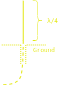
Monopole
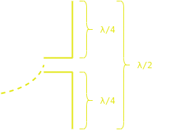
Dipole
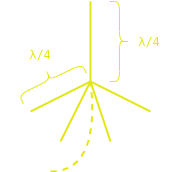
Quadrupole (45° between rods)
An antenna has always two poles, one positive and other negative. In some cases, such as the monopole, the negative pole is connected to ground plane (e.g., Earth). Different types of antenna are more suitable to certain wavelengths, e.g., in some cases monopoles can be as high as λ/2. Additionally, as the frequency increases, more specific antennas are required (e.g., dish-shaped parabolic or quadrifilar helicoidal antennas). Other antennas worth mentioning are the YouLoop Magnetic Antenna for HF frequencies, and MiniWhip which is an active antenna3 for the LF, MF, and HF bands.
Spectrum and Modes
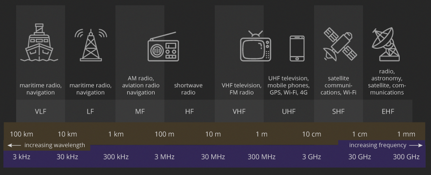
The used spectrum of radio waves is presented in the figure above (from terasense). As an example, short wave communications, one of the most know and used bands across amateur radio, operates in the High frequency (HF) spectrum. There are several organizations and legislation related to the correct usage of the spectrum, including transmission power, interferences, and spectrum allocation, see more at ANACOM (for Portugal) and ITU Radio Regulations (for international scope).
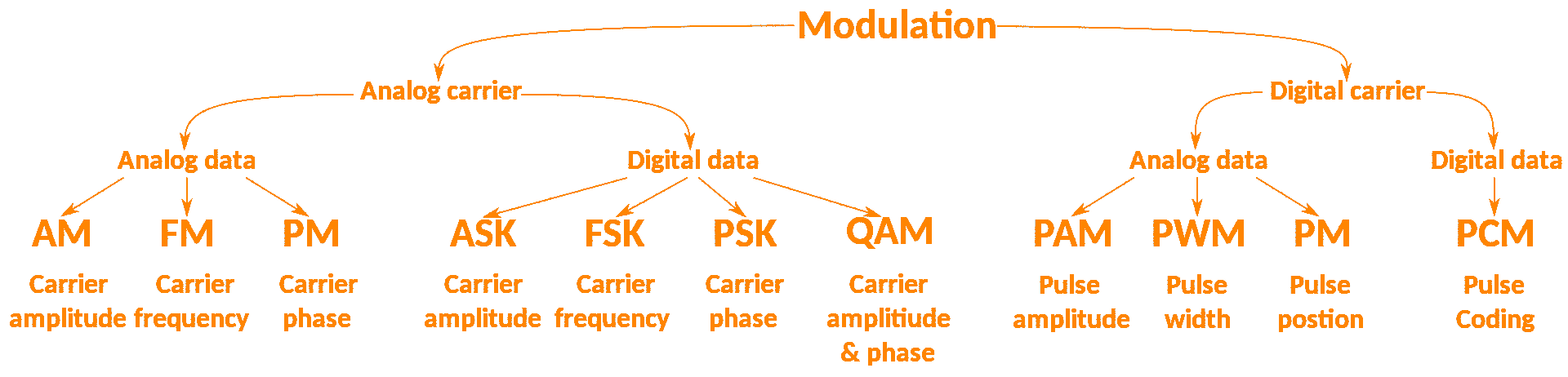
Signals that are messages are typically encoded (i.e., modulated) in radio waves using different strategies. A summary of all the different strategies is given in the figure above (left)4. The most common modulations are done by changing the amplitude and/or frequency, as shown in the animated GIF on the right. In some cases, a combination of more than one strategy is used to modulate a given signal.
For audio signals, the most common modulations are the following (which are typical present in almost all power-user radios and software):
- WFM (Wideband Frequency Modulation), a greater % of carrier is modulated to a much higher deviation to provide high fidelity;
- NFM (Narrow Frequency Modulation), a small % of the carrier is deviated and so can be spaced closer to other carriers but with very reduced fidelity;
- AM (Amplitude Modulation), the information is carried in the sidebands on either side of the carrier by injecting the sound energy onto the carrier;
- L/USB or SSB (Lower/Upper Side band or Single Side Band), similar to AM but without a carrier and all sound energy is imposed on ONE sideband;
- DSB (Dual or Double Side Band), is like AM (USB+LSB) but with no carrier;
- CW (Continuous Wave), is used for sending Morse Code, the process simply turns the carrier on and off (pure carrier).
Taken from here. Some modes / protocols can be directly decoded using multimon-ng. Example usage with rtl_fm, decoding MORSE at 433.92MHz:
$ rtl_fm -g 19 -f 433.92e6 -M am -s 200e3 -r 22050 - | multimon-ng -a MORSE_CW -t raw /dev/stdin
SDR Hardware 101
The one I bought was a Nooelec NESDR SMArt v4 SDR (~30€). This model, similarly to other popular ones, including the RTL-SDR, share the same RTL2832U chipset, which was originally developed by Realtek as a high-performance DVB-T COFDM demodulator with USB 2.0 support. Palosaari et al. found out that it was possible to access the raw I/Q data of these cheap DVB-T dongle, which was made simple by the custom software driver developed by Steve Markgraf.
There are some characteristics of these low-cost SDRs that are a good insight to their functioning (using the mentioned Nooelec as a reference):
- Approx. Frequency Range: 24MHz — 1750MHz
- Lower frequencies – i.e., shortwaves – can be reached using a cheap upconverter;
- Rx only:
- Reduces the capability of creating radio interferences and make other mistakes while experimenting with it;
- SMA Female antenna connector:
- Another adapter hell (SMA/BNC/UHF/N/F/…);
- Maximum sample rate is 3.2 MS/s (mega samples per second):
- Too low sample rates can cause problems when demodulating/decoding signals;
- Too high sample rates can have limited use since they can be downgraded due to the used communication bus (most dongles use USB 2.0) or CPU;
- ADC native resolution is 8 bits:
- This directly impacts the Signal to Noise Ratio (SNR) value that compares the level of a desired signal to the level of background noise;
- The theoretical SNR of a perfect N-bit ADC is given by 6.02 dB * N + 1.76 dB;
- This results in a ~50 dB Signal to noise ratio, but most signals do not come closer to that value;
- ~75 Ohm input impedance5:
- Most common (standard) impedance is 50 Ohm (50 Ohm cabling on a 75 Ohm input will be less than 0.177 dB);
- Impedance should be close among the components in a given setup (mismatch in impedance leads to voltage and current reflections);
- For consistency’s sake, all other hardware, antennas, and such will be considered to work at 50 Ohm.
This gives an overview of the key hardware terms of the functioning of an SDR. Other hardware concepts will be introduced as needed (filters, antennas, and others). If you don’t have an SDR, you can always use one of the available WebSDR.
SDR Software 101
Since we reduce the reliance on hardware parts, we require lots of software to complete the missing pieces. If you are using a Windows machine, SDR# from Airspy is a good place to start (and brings together all the drivers and stuff you need to start playing around).
In a Linux machine, start by installing the RTL-SDR drivers from your package manager or source. After that, it is time to start navigating in the spectrum. There are several clients, from which the next are just some:
- Gqrx, SDR receiver implemented using GNU Radio and the Qt GUI toolkit (will be used as a reference).
- SDR++, SDR software with the aim of being bloat free and simple to use.
- gnuradio, toolkit that provides signal processing blocks to implement software radios.
- SDRangel, SDR and signal analyzer frontend to various hardware.
- UHR, is a suite for wireless protocol investigation, allowing demodulation of signals combined with an automatic detection of modulation parameters.
- inspectrum, a ready-to-use radio signal analyser.
Similarly, other software will be introduced as needed.
Listening to 433Mhz Signals
Part of the industrial, scientific, and medical (ISM) radio band (which includes 433.92 MHz, 915 MHz, and 2400 MHz) is widely used for common appliances such as garage door openers, wireless alarm or monitoring systems, industrial remote controls, smart sensor applications, tires pressure sensors, and wireless home automation systems.
Due to its widespread use, this is one of the bands which is easier to receive, analyze, demodulate and decode. A simple and cheap monopole (e.g., telescopic) or dipole antenna approximately tuned to these frequencies can receive signals. In the case of a monopole, for the 433 MHz band, the λ is c / 433000000 = 69,24 cm, λ/2 = 34,62 cm, and λ/4 = 17,31 cm. Thus, for a 1/4 wave monopole, a piece of wire with ~17.31 cm should be enough.
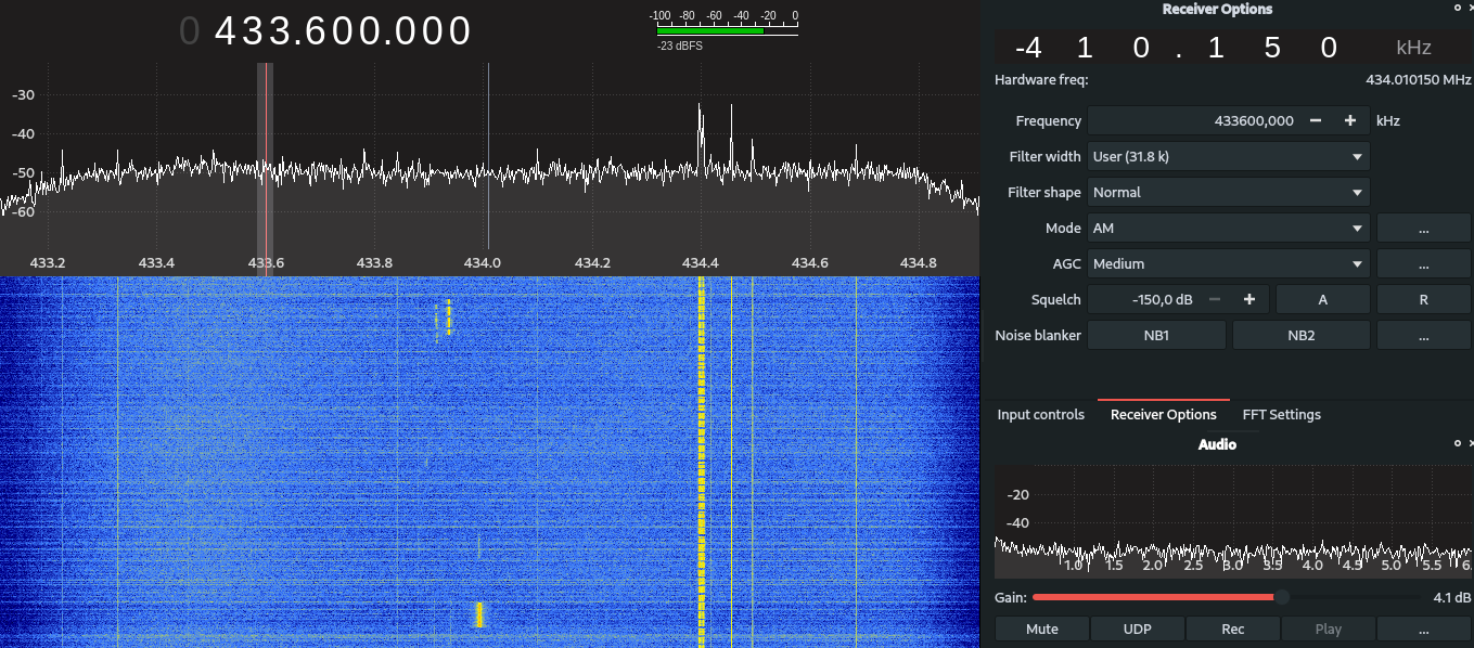
After connecting such antenna to the SDR, and the SDR to a Linux machine, we can start analyzing the spectrum with Gqrx.
We could now save the raw digital signal and analyze it manually (demodulate). There are a few guides available online on how to do it, so I will not delve into the details.
A easier and quicker way to get it done is to use the rtl_433: rtl_433 (despite the name) is a generic data receiver, mainly for the 433.92 MHz, 868 MHz (SRD), 315 MHz, 345 MHz, and 915 MHz ISM bands.
$ rtl_433
Use -h for usage help and see https://triq.org/ for documentation.
Registered 157 out of 186 device decoding protocols [ 1-4 8 11-12 15-17 19-23 25-26 29-36 38-60 63 67-71 73-100 102-105 108-116 119 121 124-128 130-149 151-161 163-168 170-175 177-186 ]
Found Rafael Micro R820T/2 tuner
Exact sample rate is: 250000.000414 Hz
Sample rate set to 250000 S/s.
Tuner gain set to Auto.
Tuned to 433.920MHz.
Allocating 15 zero-copy buffers
baseband_demod_FM: low pass filter for 250000 Hz at cutoff 25000 Hz, 40.0 us
After initialization, we start to see the first data appearing:
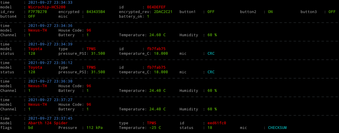
There are other interesting projects to explore on the Rx/Tx of 433Mhz signals, including RFQuack and io433, that are hardware-specific Rx/Tx tools, that support replaying messages and other attacks.
If one wishes to record the raw data to further manual analysis, one can also use a combination of rtl_433 with aplay (rtl_433 tuned to a narrow FM channel at 162.5 Mhz with a 22 Khz sample rate):
$ rtl_433 -M fm -f 433.92M -s 22k | play -t raw -r 22k -es -b 16 -c 1 -V1 -
There are other applications running on 433 Mhz, which include CubeSats. As an example, Norby cubesat transmits telemetry data using the LoRa protocol at 436.703 Mhz.
Airplanes and Stuff
There is a whole world of aircraft communications, with some being open and others encrypted. Frugal Radio has a lot of content around Rx and demodulating aircraft communications which I recommend as a good starting point. Most of aircraft communications (including Air Traffic Control Towers comms) use specific bands that are mostly well documented per airport (Porto example).
ACARS
ACARS (Aircraft Communications Addressing and Reporting System) is a digital datalink system for transmission of short messages between aircraft and ground stations via airband radio or satellite. The protocol was designed by ARINC and extended by SITA.
In Linux, we can Rx and decode ACARS messages using acarsdec.
$ acarsdec -r 0 131.525 131.725 131.825
Found Rafael Micro R820T/2 tuner
Exact sample rate is: 2500000.107620 Hz
Allocating 32 zero-copy buffers
There are several frequencies used for ACARS, the presented ones are a mere example. An example output is the following:
[#2 (F:131.725 L: -10 E:0) 27/09/2021 23:36:44 --------------------------------
Mode : g Label : SQ
00XS

[#3 (F:131.825 L: -17 E:3) 27/09/2021 23:37:11 --------------------------------
Mode : 2 Label : SQ
R14115N00841WB136975/ARINC
ACARS messages may be related to air traffic control (used to request or provide clearances), aeronautical operational control, and airline administrative control.
Airport ATC Communications
By setting Gqrx (or other client) to tune in the frequencies used by the nearby airport we are able to listen to the ATC and other plane <-> tower and plane <-> plane communications. Below is an example of the ATC Porto Arrival in AM mode (with info such as landing lanes and weather).
Aviation Transponder Interrogation Comms
The aviation transponder interrogation modes are the standard formats of pulsed sequences from an interrogating Secondary Surveillance Radar (SSR) or similar Automatic Dependent Surveillance-Broadcast (ADS-B) system. The reply format is usually referred to as a “code” from a transponder, which is used to determine detailed information from a suitably equipped aircraft.
1090 MHz is the standard for ADS-B reporting. With a tool such dump1090 one can scan for transmitted messages and plot them in a map (by visiting localhost:8080).
$ dump1090 --modeac --aggressive --net --interactive
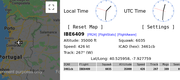
Most of the flight radar websites use crowdsourced data from ADS-B scanners around the world. You deploy one for free if you are in an area that is yet to be covered, more info here (flightradar24) and here (FlightAware).
Receiving Weather Images
There are several weather satellites deployed in different Earth orbits. While most recent ones use above 1Ghz signals (requiring more specialized antennas and material), some use more friendly bands in the VHF range and broadcast APT (Automatic Picture Transmission) / LRPT (Low Resolution Picture Transmission) signals which are easily decoded using existent software tools. Some examples are the NOAA and some Meteor ones.
- NOAA 15 – 137.6200 MHz (APT)
- NOAA 18 – 137.9125 MHz (APT)
- NOAA 19 – 137.1000 MHz (APT)
- Meteor-M N2 — 137.1 MHz (LRPT)
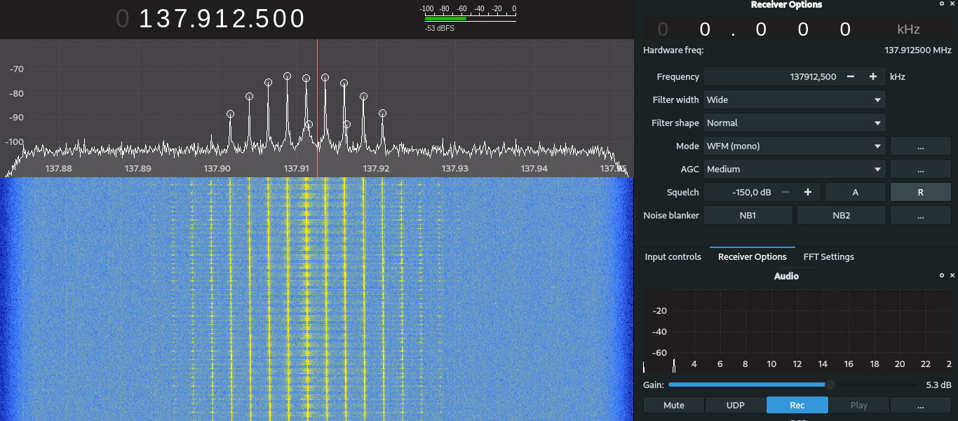
The post by Lucas Teske gives detailed info on how to configure Gqrx for capturing the signal. Summarizing the key points:
- 40kHz bandwidth required: set the decimation to 32x, and 2.56Msps of input rate (sample rate);
- Filter width: Wide; Filter Shape: Normal, Mode: WFM (mono)
- Hardware AGC: off, Swap I/Q: off, No Limits: off, DC Remove: on, IQ Balance: on, and LNA Gain: 20dB.
However, depending on your SDR and setup, you can (and should) play around with these settings until you reach the best results.
As these satellites orbit the Earth they only transmit images to a certain point of the globe at a given window. One can easily track the satellites in real-time using Gpredict or Look4Sat (Android App).
The image bellow is an example of an APT signal being received. There are several guides on how to configure the receiving software and how to build proper antennas for receiving data from these satellites, including a good post from RTL-SDR blog which gives some info on it. By experience, either a well-made and correctly oriented V-dipole or a poorly-made QFH antenna gives the best results.
APT signals can be decoded using software such as the noaa-apt image decoder. The best result I got with a dipole from a balcony was the following:
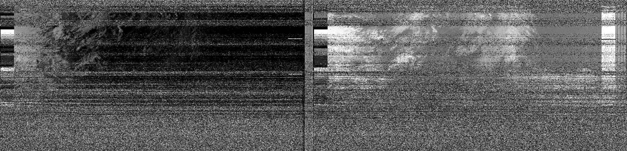
Note: While receiving signals from space you have to deal with Doppler effect, i.e., periodically adjust the frequency to center the signal as it moves.
ISS Signals
The International Space Station can be considered an enormous transmitter station. Both voice and SSTV signals are transmitted in a regular basis on the 145.8 MHz band.
Slow Scan Television (SSTV) is transmitted by the ARISS Russia Team from the amateur radio station in the Russian Service Module of the International Space Station using the callsign RS0ISS. (…) The ISS puts out a strong signal on 145.800 MHz FM and a 2m handheld with a 1/4 wave antenna will be enough to receive it. (From amsat-uk)
Similarly to the NOAA satellites, I would say that a V-dipole or QFH is good enough. You can find more information about ARISS on the official website, including the schedule for planned SSTV transmissions.
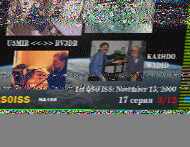
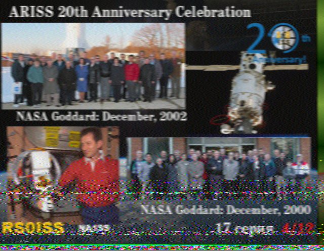
Above are some SSTV pictures that I managed to receive in the past. When you successfully receive a SSTV image you can apply for the corresponding ARISS SSTV diploma (typically consisting on filling a Google Forms, but it is unique for each Rx event).
Navigation and Mobile Comms
GPS
The number one navigation system deployed in almost all smartphones uses satellites to triangulate your position (in reality, typically, the location given by a smartphone uses other data sources including mobile stations information and others).
At this moment there are 6 GPS systems deployed in orbit: BeiDou (China), Galileo (EU), GLONASS (Russia), GPS (USA), NavIC (India), and QZSS (Japan). There are five main bands used for these satellites, namely:
- L1 (1575.42 MHz), broadcasts CDMA encoded messages, namely, the coarse/acquisition (
C/A) code, which is accessible by the general public, and the preciseP(Y)code, which is encrypted (U.S. military); - L2 (1227.60 MHz),
P(Y)code, plus theL2C(second civilian signal), and military codes; - L3 (1381.05 MHz), used for nuclear detonation (
NUDET) detection; - L4 (1379.913 MHz), studied for additional ionospheric correction;
- L5 (1176.45 MHz), proposed for use as a civilian safety-of-life (
SoL) signal.
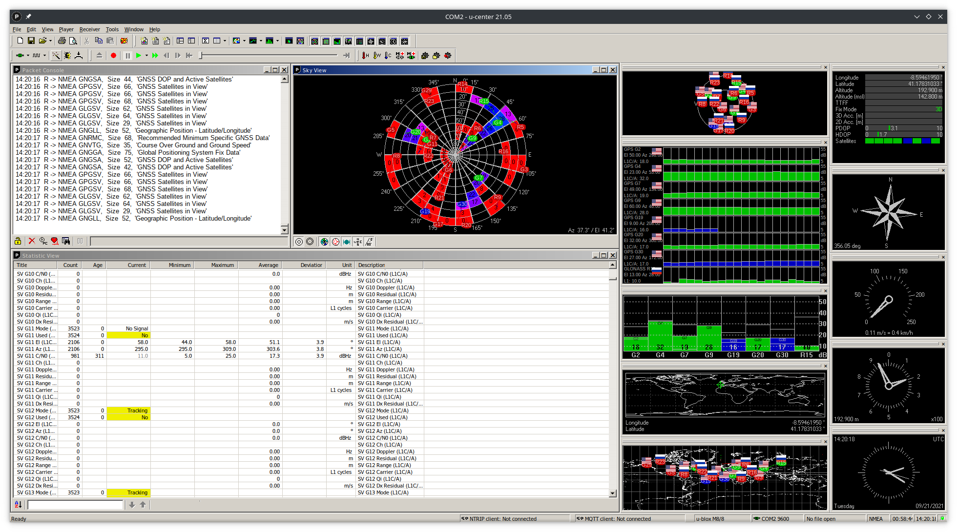
Since we cannot decrypt the military-only messsages, we can only use and plot the C/A messages. For such, we can use either GNSS-SDR software that is compatible with almost any SDR (all frequencies fall within the range of capture of a standard SDR), or use a dedicated GPS reciever, such as the u-blox ones.
u-blox provides a software to experiment with GPS reception named u-center. The older version, u-center for Windows v.21.05, is compatible with Wine (just bridge the serial port to the corresponding Wine COM port), thus can be used in a Linux machine. This following image shows a lock on the coordinates of FEUP building, Porto.
GSM, LTE, 3G, …
Cellular frequencies are the sets of frequency ranges within the ultra high frequency band that have been assigned for cellular-compatible mobile devices, such as mobile phones, to connect to cellular networks. (from Wikipedia)
There are a lot of frequencies that are used for cellular comms, depending on the version that you are using and where you are located (ITU Regions). As an example, the first GSM version adopted in Europe used the 900 MHz band (lower frequency band that allow carriers to provide coverage over a larger area), while nowadays most use the 1,800 MHz band (band that allows carriers to provide service to more customers in a smaller area). This resulted in many GSM devices supporting several frequencies (e.g., 850/900/1,800/1,900 MHz). More info available on Wikipedia.
As a motivational example, one can use the gr-gsm tool package to inspect cellular signals.
grgsm_scannergives a list of the used frequencies;grgsm_livemon -f 925.4Mto decode GSM signals in the925.4 Mhz.
One popular application among surveillance community is the use of IMSI catchers that collect unique identification of the phones in a given area (data includes IMSI numbers, country, brand, and operator). A PoC of such tool is available here (please remember Disclaimer 1).
Understanding how mobile communications work is another story, and there is a lot of content around BTS stations and such.
Weather Forecasts, Number Stations, and World Radio
In the short wave spectrum we can find a lot of signals, ranging from Morse code comms to mysterious cold war signals. The following are a few examples of what one can find in these waves.
VOLMET stations
One of the most easy to capture signals in the Short Wave band are the VOLMET stations:
VOLMET (French origin vol (flight) and météo (weather report)), is a worldwide network of radio stations that broadcast TAF, SIGMET and METAR reports on shortwave frequencies, and in some countries on VHF too.
Example audio from a Shannon VOLMET station (Republic of Ireland on 5505 kHz):
Number Stations
A numbers station is a shortwave radio station characterized by broadcasts of formatted numbers, which are believed to be addressed to intelligence officers operating in foreign countries (from Wikipedia).
There is a lot of lore and theories about the use of number stations beyond the cold war period. However, the reality is, that some stations keep transmitting today in well known frequencies. The Priyom organization focuses on research and bring to light the mysterious reality of intelligence, military and diplomatic communication via shortwave radio. They have a list of known radio stations, including their broadcasting schedule, mode, and target area. I still haven’t managed to receive number stations comms using my radio setup, but you can easily pick one up using a WebSDR.
One of the most known stations is UVB-76, aka The Buzzer, captured from a Russian WebSDR:
World Radio
There are a lot of radio stations being broadcasted in short wave. You can find them here. You can also use the website to find out which radio is transmitting in a given frequency. Most of the transmissions are AM, but you can already find some FM ones too. Next is an example of BBC radio on 7.445 MHz giving some football news.
FST4, FST4W, FT4, FT8, …
WSJT-X implements communication protocols or “modes” called FST4, FST4W, FT4, FT8, JT4, JT9, JT65, Q65, MSK144, and WSPR, as well as one called Echo for detecting and measuring your own radio signals reflected from the Moon. These modes were all designed for making reliable, confirmed QSOs under extreme weak-signal conditions.
The digital signal processing techniques in WSJT make it substantially easier for amateur radio operators to employ esoteric propagation modes, such as high-speed meteor scatter and moonbounce (from Wikipedia).
Receiving these signals can be a little complex due to the number of different software necessary. This post by Cornelius presents it clearly. Summarily:
- Create a virtual cable to pass the raw audio data between GQRX and WSJT-X;
$ pacmd load-module module-null-sink sink_name=Virtual_Sink sink_properties=device.description=Virtual_Sink
- Open GQRX, change the audio output to the
Virtual_Sink, and note down the UDP Remote control address (default is127.0.0.1:7356); - Open WSJT-X and set the following configurations:
- (Radio) Select the
Hamlib NET rigctlrig and insert the GQRX address; - (Audio) Select
Virtual_Sink.monitor; - (Main Window) Select the target mode (e.g.,
FT8).
- (Radio) Select the
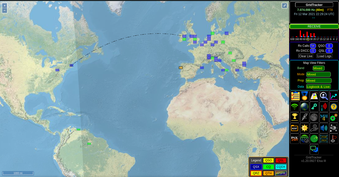
- Lastly, open GridTracker to plot the data comms in a map. More Info.
With a cheap YouLoop antenna I was able to receive messages from long distances (see figure bellow). Once again, for transmitting signals and confirm the reception (e.g., DX contests) an amateur radio license is required in Portugal.
On the case of Shortwave
HF signals are highly-sensible to solar activity, i.e., solar activity can aid or hamper HF propagation beyond line-of-sight range. More info here. A common plot of relevant solar activity that is present around amateur radio websites is the following, that provides the most recent data about solar events and its influence in the radio bands. Similarly, some bands work better during daytime and others during nighttime.
1.8Ghz and Beyond
The SDR I have only works until ~1.8GHz. However, we work every day with signals above that (mainly last parts of the UHF band), including Wi-Fi (2.4GHz and 5GHz), Bluetooth, and other IoT protocols. You can also start exploring those signals, e.g., using Wi-Fi chipsets which support monitor mode and other tools. But that’s a story for another post.
Other signals, that are part of the SHF and EHF bands, require large dishes and special equipment ($$$++) just to start exploring…
A final note of thanks to Zezadas for some useful insights to this post.
Other links
- Where and which SDR to buy?
- SDR quick start guide
- Shortwave Radio Guide
- Decoding POCSAG (Pager) Signals
- Lessons on Software Defined Radio with HackRF by Great Scott Gadgets
- Signal Identification Wiki
References
-
An active antenna is an antenna that contains active electronic components such as transistors (…) and are primarily used in situations where a larger passive antenna is impractical, Active antenna, Wikipedia ↩
-
Impedance of the electrical load should matche the impedance of the power or driving source. ↩